
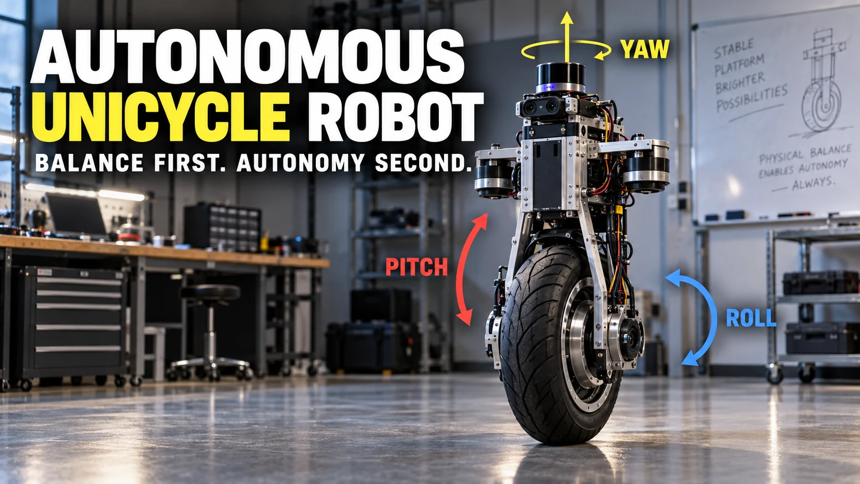

Yes, an unmanned unicycle robot can be built, but the hard part is not “AI” – it is stabilizing an underactuated one-wheel platform in pitch and roll while still controlling motion. Modern prototypes do this with a drive motor plus a lateral-balancing mechanism such as a reaction wheel, gyroscope/control-moment mechanism, or omnidirectional lateral drive, then add sensors and higher-level autonomy on top. The practical build order is mechanics first, fast feedback control second, and perception or path planning last.
The original idea behind this page was directionally right about one thing: a riderless unicycle needs continuous correction to keep its center of mass over a very small ground contact. What has changed is the engineering vocabulary and the available evidence – current single-wheel robot research treats the problem as a mechatronics and control task, with artificial intelligence useful mainly at higher levels such as perception, navigation, adaptation, or planning.
| Robot job | What must do the work | Why it matters |
|---|---|---|
| Stay upright front-to-back | Wheel drive + attitude feedback | The wheel must move under the falling center of mass. |
| Stay upright side-to-side | Reaction wheel, gyro/CMG, or lateral-drive mechanism | A normal single wheel cannot simply steer sideways fast enough to recover from every roll disturbance. |
| Know its state | IMU, wheel encoder, and usually additional feedback | Control depends on reliable angle, angular-rate, and motion estimates. |
| Move autonomously | Localization, perception, route logic, and supervisory software | Autonomy decides where to go; the balance controller still has to keep the platform upright. |
The key correction: balancing is a control problem before it is an AI problem
A modern self-balancing unicycle should be thought of as an unstable dynamic system with several control loops, not as a machine that becomes stable once an “AI brain” is installed. Research on single-wheel platforms has demonstrated successful balancing with classical linear control, sliding-mode and feedback-linearization methods, adaptive fuzzy control, and related approaches, which means the essential stabilizing behavior does not require a general-purpose AI model.
The GYROBO single-wheel research is a useful example because the authors improved performance not only through control software but also by relocating components, improving symmetry, reducing vibration, and iterating the physical assembly. That is a practical lesson for any hobby or research build: software cannot cleanly compensate for a chassis whose geometry, mass distribution, or actuator behavior keeps changing.
For a broader foundation, our guide to robotics and the role of technology in robotics explains why sensing, actuation, computation, and feedback have to work as one system. If the build is described as “AI,” the useful question is still what the AI is actually responsible for – balance, perception, decision-making, or route selection.
What a workable single-wheel robot needs
A practical prototype needs enough hardware to observe the falling motion, generate corrective torque, and survive repeated testing. The exact parts vary by architecture, but the functional jobs stay consistent across serious designs.
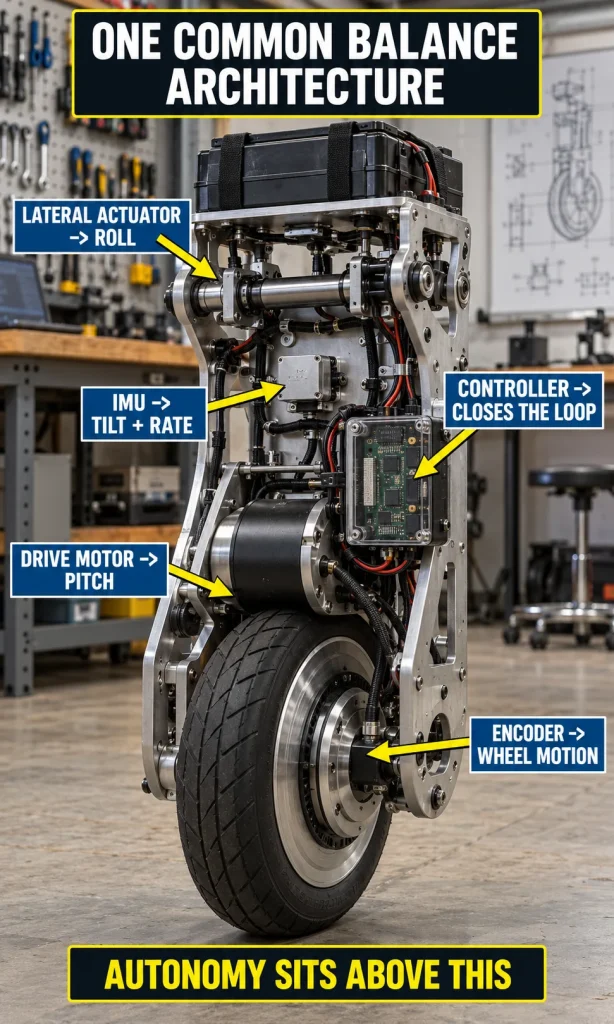
- Rigid single-wheel chassis: the frame must keep the wheel, actuators, sensors, and major masses in known positions.
- Drive motor: controls forward/backward wheel motion and is normally part of pitch stabilization.
- Lateral-balance actuator: usually a reaction wheel, a gyroscope/control-moment mechanism, or a lateral-drive arrangement.
- IMU: provides angular-rate and acceleration data used to estimate attitude.
- Wheel encoder: measures wheel motion so the controller can separate body angle from travel behavior.
- Real-time controller: runs the attitude estimation and motor-control loops deterministically enough for the platform dynamics.
- Power system: battery, motor drivers, regulators, current protection, and an emergency-stop strategy.
- Catch rig or tether: protects people and hardware while the controller is still learning how not to fall.
A camera, depth sensor, or LiDAR can become important later, but those sensors do not replace the fast attitude loop. If the robot cannot hold pitch and roll on a controlled test rig, adding object detection or route planning only increases complexity without fixing the core instability.
How pitch, roll, and yaw are controlled
Pitch is the front-to-back falling motion. The usual correction is conceptually similar to other inverted-pendulum vehicles: when the body begins to fall, the drive wheel accelerates so the contact point moves back under the center of mass; the controller then reduces the correction before the robot overshoots.
Roll is harder because the single tire offers very little direct side-to-side correction while the robot is standing or moving slowly. A unicycle therefore needs another way to create lateral torque, and that is where reaction wheels, gyroscopic precession, or a lateral-drive mechanism become central to the design.
Yaw is rotation around the vertical axis. Depending on the architecture, yaw can be influenced by wheel steering geometry, gyroscopic effects, differential internal motion, or a dedicated mechanism; the important engineering point is that roll and yaw may be coupled, so tuning one loop as if the other does not exist can produce unstable behavior.
The unicycle balance-control work from National Cheng Kung University illustrates one common arrangement: a main wheel for longitudinal stability and a reaction wheel for lateral stability. Other designs use different hardware, so a good controller starts from the actual mechanics rather than forcing every platform into one generic model.
Three lateral-balance architectures worth comparing
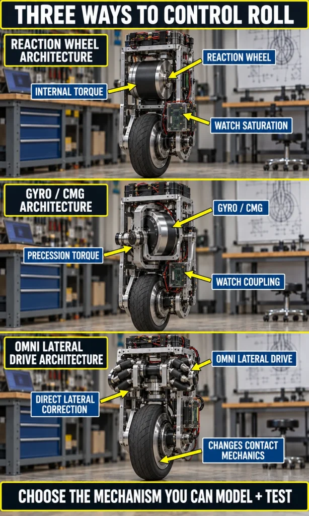
No single roll-control mechanism is universally best. The right choice depends on packaging, available torque, energy, desired speed, yaw behavior, mechanical complexity, and whether the project is a stationary demonstration or a mobile autonomous platform.
| Approach | How it corrects roll | Main advantage | Main design challenge |
|---|---|---|---|
| Reaction wheel | Changes internal angular momentum to create corrective body torque. | Mechanically understandable and suitable for a compact proof-of-balance architecture. | Momentum and speed limits can cause actuator saturation. |
| Gyroscope / CMG | Uses gyroscopic precession to generate lateral control torque. | Can provide strong disturbance rejection in a compact rolling platform. | Coupling, precession dynamics, packaging, and mechanical complexity. |
| Omnidirectional lateral drive | Creates direct lateral motion through a roller or omni mechanism. | Provides a more direct lateral correction path. | Changes the contact mechanics and may no longer behave like a conventional single-tire unicycle. |
Recent unicycle robot research using an omnidirectional wheel mechanism demonstrates that lateral balancing can be approached by changing the wheel-ground interaction itself. By contrast, double-gyroscope unicycle research uses precession and adaptive fuzzy control to address lateral balance and coupling disturbances, showing why the mechanical architecture and the controller must be designed together.
Why the original moving-weight idea is possible but awkward
Moving a mass to the opposite side of a fall can create a corrective shift in the center of mass, so the original concept is not physically meaningless. The difficulty is that a sliding or rotating ballast system has to move far enough and fast enough, then reverse without introducing new oscillation, while adding weight, guides, actuators, and structural loads.
For an early prototype, a reaction wheel or a better-understood gyroscopic mechanism is usually easier to model because the relationship between actuator motion and corrective torque is more direct. If a moving-mass system is part of the research question itself, it should be treated as an actuator that needs its own dynamic model and saturation limits rather than as a simple “weight moves left when the robot falls right” rule.
Build it in this order
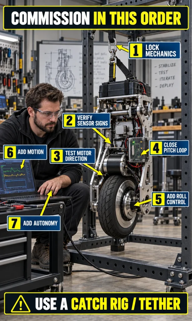
The safest path is to separate the project into stages where each new layer depends on something already proven. This keeps a navigation bug from being confused with a balance problem and makes failures much easier to diagnose.
- Lock the mechanics. Build a rigid chassis, secure every heavy component, measure wheel radius and major mass locations, and keep the center of mass repeatable between tests.
- Verify sensor signs. Confirm that positive pitch, roll, yaw, wheel rotation, and motor commands all use a consistent coordinate convention.
- Test motor direction at low authority. A sign error can turn a stabilizing controller into a fall amplifier immediately.
- Close the pitch loop on a supported rig. Prove forward/backward recovery before combining it with lateral control.
- Add the roll actuator. Tune lateral recovery while watching for pitch-roll and roll-yaw coupling.
- Add commanded motion. Introduce forward speed, stopping, and turning without allowing motion commands to override attitude safety limits.
- Add autonomy last. Localization, obstacle sensing, route planning, and behavioral logic should supervise the already-stable low-level control system.
If you want a compact way to identify the next dependency in your own prototype, use the experience below. It deliberately returns a build stage and test sequence rather than a made-up “readiness percentage.”
Single-wheel robotics decision support
Autonomous Unicycle
Design Studio
Separate the balancing problem from the autonomy problem, identify your next engineering stage, and generate a practical test sequence without fake precision.

It does not calculate a made-up readiness score. It identifies the next stage your prototype should prove before you add more autonomy.
NEXT ENGINEERING STAGE
Mechanical bench stage
Architecture direction
Main blockers to clear
Commissioning sequence
Where AI can genuinely help
Once the balancing controller is reliable, artificial intelligence can become useful for tasks where the robot has to interpret a less predictable environment. Examples include object recognition, terrain classification, learned state estimation, adaptive control elements, route selection, anomaly detection, or policies that decide how aggressively the robot should move under changing conditions.
That distinction is useful beyond this project. Our explanation of how AI systems make decisions covers the higher-level reasoning side, while computer vision becomes relevant when the unicycle needs to detect obstacles or interpret scenes. Neither changes the requirement for a deterministic, well-tested stabilization layer underneath.
Failure modes that usually appear before “better AI” is the answer
A single-wheel robot can fail even when the code looks mathematically reasonable because the physical system is full of delays, saturation, vibration, friction, sensor bias, and coupling. The useful debugging question is therefore not “Which AI model should I add?” but “Which state estimate, actuator limit, or mechanical assumption is wrong?”
| Symptom | Likely class of cause | Check next |
|---|---|---|
| Falls faster after controller engages | Sign or axis error | IMU orientation, encoder direction, motor polarity, coordinate convention |
| Balances briefly, then oscillates harder | Gain, delay, structural flex, or filtering problem | Loop timing, phase lag, vibration, loose frame, actuator bandwidth |
| Roll recovers but yaw swings unexpectedly | Coupled mechanics | Gyro/reaction-wheel coupling and yaw-control assumptions |
| Works in the rig but fails during motion | Operating-point change or saturation | Speed-dependent dynamics, actuator headroom, friction, command limits |
| Navigation works but the robot still falls | Autonomy added before stabilization was mature | Separate the balance loop from perception and planning, then revalidate each layer |
The same layered thinking is useful when evaluating AI safety and system safeguards: higher-level intelligence should not be allowed to bypass hard physical limits, emergency-stop behavior, or well-understood low-level control constraints. For a small research prototype, that means conservative actuator limits, a protected test area, a reliable kill mechanism, and staged testing before free operation around people.
What a credible first prototype should prove
A first prototype does not need to navigate a building to be a successful engineering result. If it can hold itself upright on a catch rig, recover from controlled disturbances, drive a short commanded path without destabilizing, stop predictably, and repeat those behaviors without hardware shifting between runs, the project has already solved the hardest part of the original concept.
From there, the autonomy layer can grow deliberately: add wheel odometry, then localization, then obstacle sensing, then route logic, and only then more sophisticated adaptive or learned behavior if the use case justifies it. This is where “artificial intelligence” becomes meaningful because it is solving uncertainty in the environment rather than being used as a vague label for basic feedback control.
Frequently Asked Questions
Can a robot really balance on one wheel with no rider?
Yes. Research prototypes have demonstrated single-wheel balancing using combinations of wheel drive, reaction wheels, gyroscopes, and other lateral-control mechanisms. The difficulty is keeping pitch, roll, and yaw behavior stable at the same time, especially when the robot begins moving or encounters disturbances.
Does a self-balancing unicycle need artificial intelligence?
No. The core stabilization problem can be solved with conventional control methods if the mechanics, sensors, model, and actuators are suitable. AI becomes more useful for perception, navigation, adaptation, or higher-level decision-making after the low-level balance system works reliably.
What keeps the robot from falling sideways?
The design needs a lateral-control mechanism because the main wheel alone cannot provide every side-to-side correction. Common research approaches include reaction wheels, gyroscopic or control-moment mechanisms, and architectures that create direct lateral motion.
Should I add a camera before tuning the balance controller?
Usually no. A camera can help with autonomous navigation, but it does not replace the high-rate attitude and wheel-motion feedback used for stabilization. Prove pitch and roll on a safe rig first, then add perception as a separate supervisory layer.
Is a moving-weight balancing system a bad idea?
Not necessarily, but it is mechanically demanding. A moving mass can shift the center of mass and create corrective motion, yet the travel distance, actuator speed, added weight, structural loads, and oscillation risk all have to be modeled. For a first proof of concept, a reaction-wheel or gyroscopic approach is often easier to analyze and test.
Next steps
Keep the existing URL, replace the old speculative copy with a control-first explanation, and treat the project as a staged mechatronics build rather than an “AI first” experiment. Start with a safe mechanical rig, prove the attitude loops, validate disturbance recovery, and only then add motion and autonomy; that sequence turns the original idea from a thought experiment into a testable engineering program.